Enclosure Installation Guide
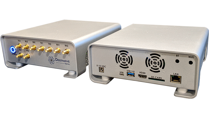
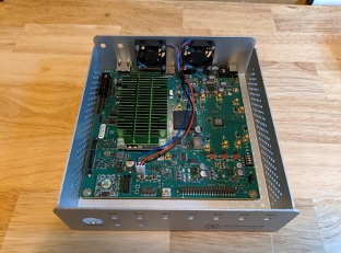
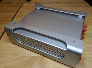
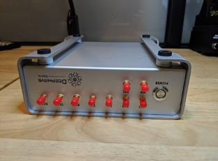
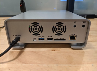
The enclosure is expertly constructed from aluminum to produce a polished, elegant, and sleek metallic silver finish. It measures 192 x 182 x 79 mm (7.5 x 7.2 x 3.1 inches) and the power button illuminates blue when the system is on. All RF ports are brought to the front of the enclosure for ease of use and all computer peripheral connections are brought to the rear.
Kit Contents
- 1 x AIR-T enclosure housing (base + cover) with power button and exhaust fans installed
- 9 x MMCX to SMA Cables * 1 x zip tie to secure power cables
- 4 x M3 hex-drive screws to secure AIR-T board to enclosure (mounted on internal standoffs)
-
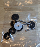
4 x Aluminum spacers
-
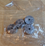
4 x Rubber feet, 4 x M3 long screws, and 4 x shock absorbing pads
Installation Instructions
-
If a heatsink was provided, peel the sticker off the bottom side of the heatsink and mount it to the GPU module using the provided screws as shown in the figure below.
-
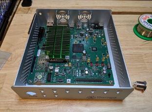
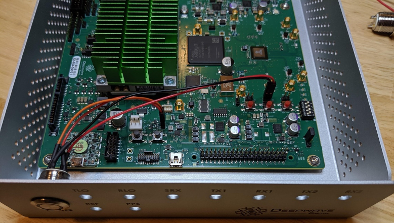
Using the provided M3 screws, mount the AIR-T PCB in the enclosure base as shown in the following figure
-
If not already done, install the fan assembly into the enclosure base
-
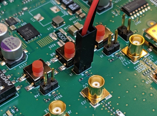
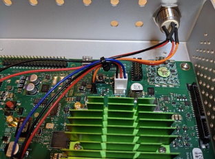
Connect the red/black cable from the power button to J6, with the red lead connected to the dot on the solder mask
-
Connect the red/yellow cable to CR2 with the red lead connected to the pin nearest the dot on the solder mask.
-
When finished the power button cable assembly should look like this:
-
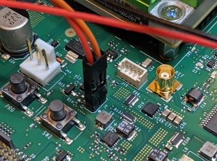
Connect the fan cable to J44 as shown in the figure and secure the fan cables and power button cables together with the provided zip tie:
-
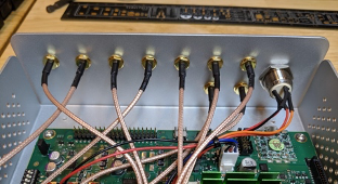
Attach all of the SMA-to-MCX cables to the front panel of the enclosure base and then connect the cables to the AIR-T, one-by one until all 9 cables have been installed.
-
If desired, install the BlueTooth and WiFi reverse polarity SMA-to-MMCX cables. These are not included in the kit and may be purchased.
- Cable Assembly Coaxial U.FL (UMCC), IPEX MHF4 to RP-SMA Female to Male Coaxial Cable (20cm), PulseLarsen Antennas, Part Number W9037BD0200.
-
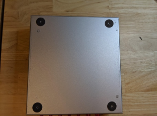
With the enclosure base turned upside down, place the shock absorbing pads over the screw holes on the bottom of the base.
-
Slide the enclosure cover over the base and insert the aluminum spacers between the cover and the base, centering the spacers over the shock absorbing pads and ensuring that the holes in the cover, spacers and base are aligned:
-
Place the rubber feet over the holes in the cover and install the long M3 screws through the feet to secure the cover to the base.
-
Now plug in the AIR-T and press the power button. If you have completed assembly correctly, the power button will show a solid blue light, the AIR-T will power on, and the exhaust fans will begin spinning.

-
Enjoy your GPU enabled SDR!
PDF Download
You can download a pdf of this document here.