Edge Series Product Guide


| AIR-T Model | GPU | FPGA | Part Number (with Enclosure) |
|---|---|---|---|
| AIR8201 | NVIDIA Jetson TX2i | Xilinx Artix7 200T | AIR8201-B |
Document Overview
This document lists the specifications for the Edge Series Artificial Intelligence Radio Transceiver (AIR-T). Specifications are subject to change without notice. For the most recent device specifications, refer to http://docs.deepwavedigital.com.
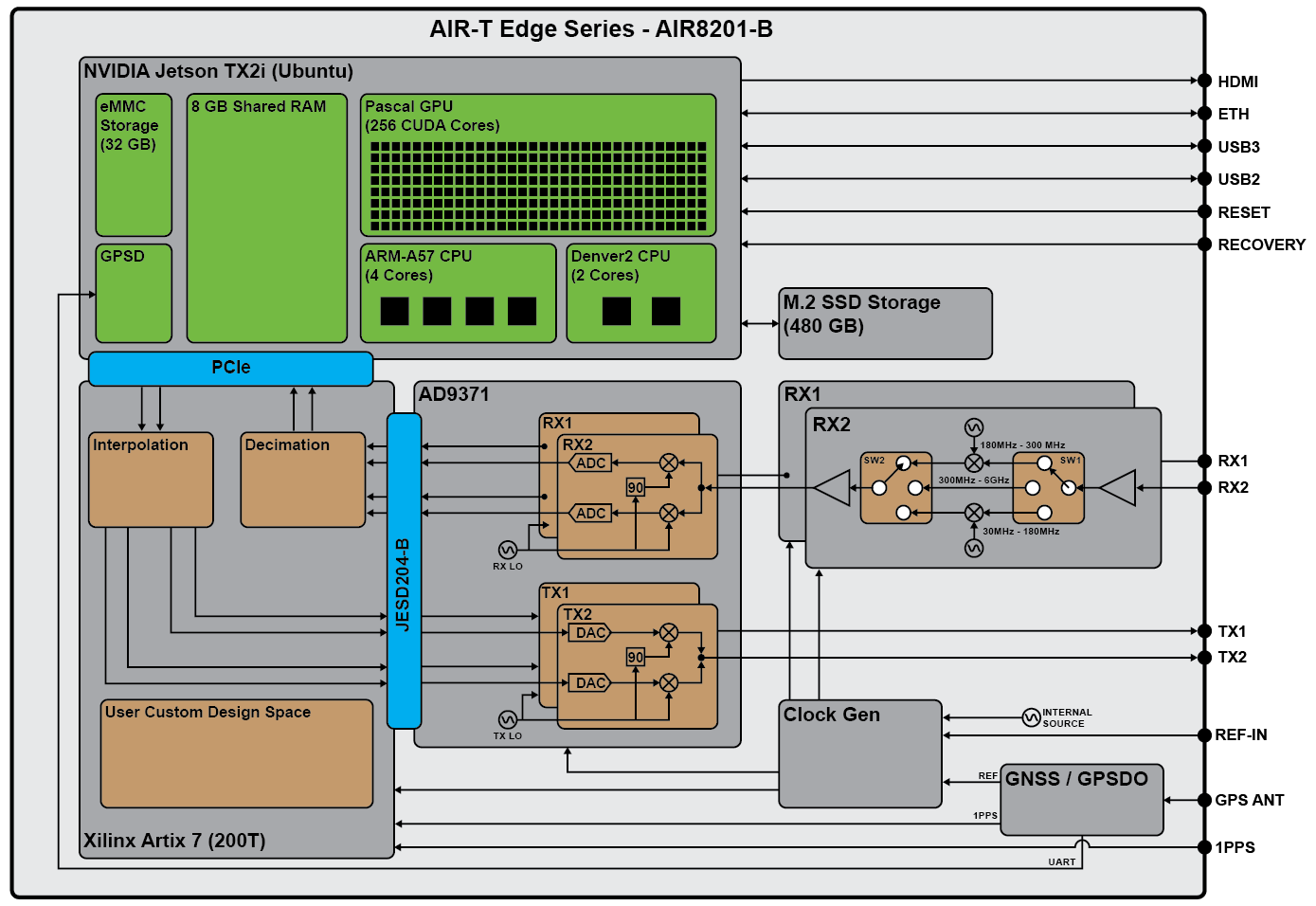
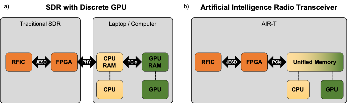
Block Diagram
AirStack Software
The AIR-T comes pre-loaded with a full software stack, AirStack. AirStack includes all the components necessary to utilize the AIR-T, such as an Ubuntu based operating system, AIR-T specific device drivers, and the FPGA firmware. The operating system is based off of NVIDIA JetPack SDK and is upgraded regularly. Please check for the latest software at www.deepwavedigital.com.
For a full description of the AirStack interface, see our documentation page here.
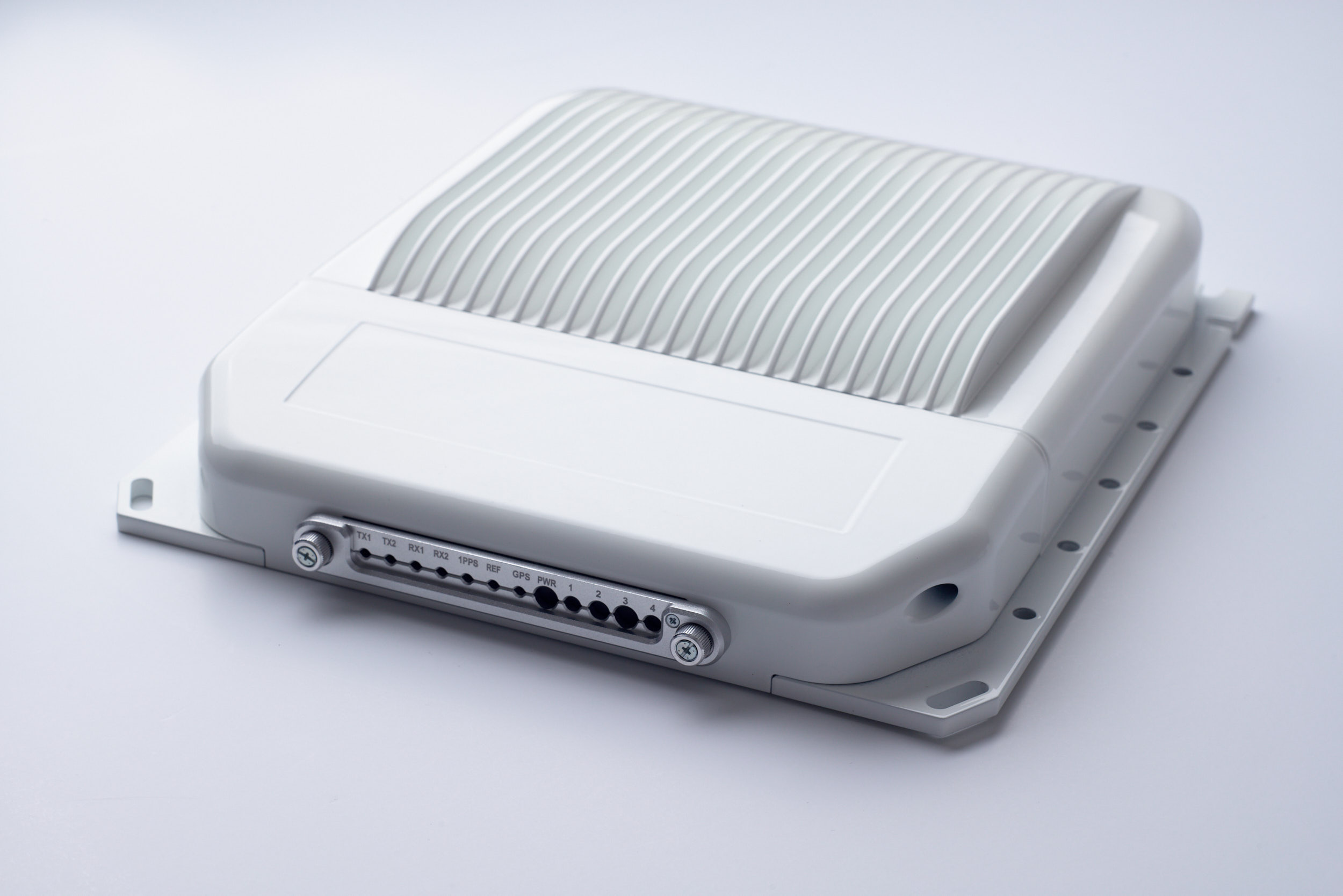
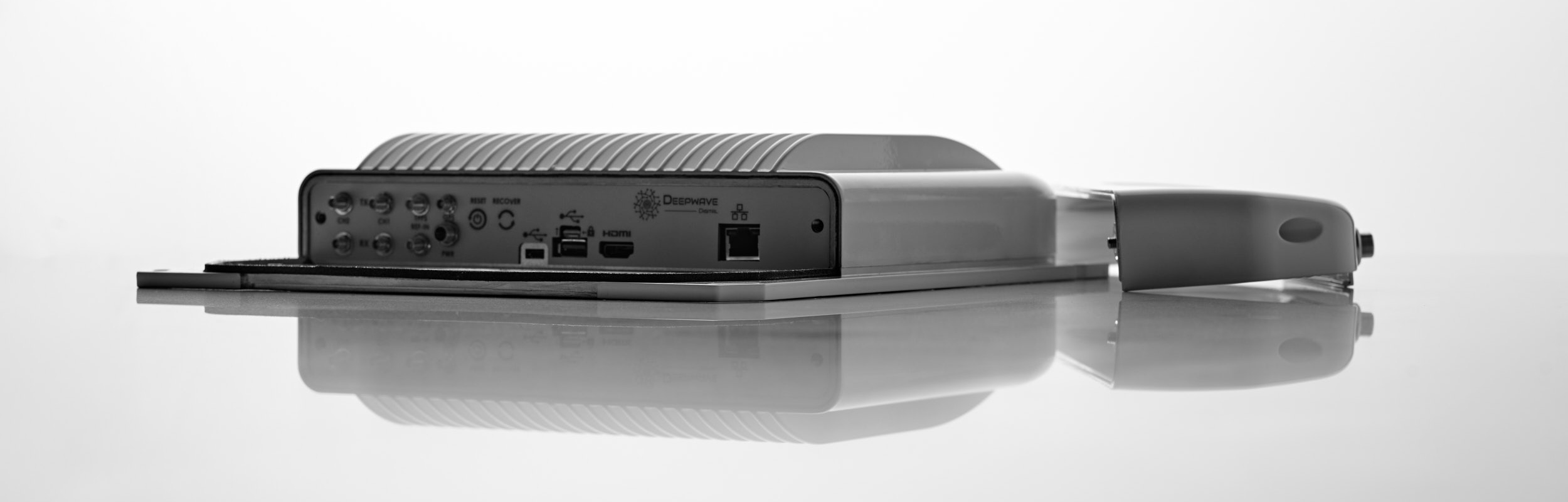
AIR-T Edge Series Ruggedized Enclosure
The AIR-T Edge Series includes a conduction-cooled, IP56 rated1, aluminum enclosure designed to handle harsh weather conditions. The SDR may be deployed on a vehicle, tower, or other outdoor environment. All RF, data, and interface ports are brought out to the front panel of the product and a form-fitting cover protects the sensitive components from the environment. Connectivity to the ports is obtained by passing cables through the water-tight front membrane seal. The front membrane seal ensures protection against harsh weather conditions.
Mechanical Drawing
We provide a PDF file with the mechanical dimensions of the AIR-T enclosure below.

Processors
The AIR-T enables software defined radio for any signal processing application by utilizing three classes of tightly coupled processors:
- FPGA for strict real-time operations
- GPU for highly parallel processing and machine learning
- CPU for control, I/O, DSP, and software applications
General Purpose Processors
The Edge Series AIR-T uses the NVIDIA Jetson TX2i System On Module (SOM) as its General Purpose Processor (GPP). The Jetson TX2i SOM contains two ARM processors (6 cores total), an NVIDIA Pascal GPU (256 cores), and 8 GBytes of memory. The CPUs and GPU all share a common pool of memory, which (along with a unified memory architecture) allows for a zero-copy capability. As illustrated in the figure below, zero-copy eliminates the host-to-device (or device-to-host) memory transfer that is required by SDRs with discrete GPUs, such as an SDR connected to an external laptop or computer. Because of this, an SDR with a discrete GPU will have increased latency that is prohibitive for many applications. By utilizing this zero-copy architecture to remove extra data transfers, the AIR-T minimizes latency compared to other SDR architectures.
The Jetson TX2i module is a version of the Jetson module designed for operations in a wider temperature, shock, and vibration range. For additional details on the NVIDIA Jetson TX2i please see the module datasheet URL below.
 Jetson Modules Technical Specifications
| Parameter | Value |
|---|---|
| Manufacturer | NVIDIA Corporation |
| Model | NVIDIA Jetson TX2i (GPU / CPU) |
| Packaging | System on Module (SOM) |
| GPU Type | NVIDIA Pascal GPU architecture with 256 NVIDIA CUDA cores (1.3 TFLOPS) |
| CPU Type | ARMv8 (64-bit) heterogeneous multi-processing CPU architecture with two CPU clusters (6 processor cores) connected by a coherent interconnect fabric. ARM Cortex -A57 MPCore (Quad-Core) Processor:
|
| Unified Memory (GPU/CPU shared) |
|
| Storage Capacity |
|
Xilinx FPGA
The FPGA on the Edge Series AIR-T comes pre-loaded with the AirStack firmware to support transmit and receive functionality at continuously variable sample rates. Customers may choose to load custom firmware if needed by their application and Deepwave will provide the FPGA interface documentation. The interface documentation includes the pin constraints file and a document that outlines the various interfaces for the FPGA so that customers may develop their own custom IP cores from scratch, i.e., without leveraging any of the AirStack software or driver infrastructure. If customers wish to leverage the AirStack software and driver infrastructure, they are encouraged to purchase a license to the AIR-T FPGA development kit, AirStack Sandbox.
The high-level details regarding the FPGA on the AIR-T are shown below.
| Parameter | AIR8201-B |
|---|---|
| Manufacturer | Xilinx |
| Family | Artix-7 |
| Model | XC7A200T-2FBG676I |
| LUTs | 215,360 |
| DSP48E1 Slices | 740 |
| Embedded Block RAM | 13.14 kbits |
| Default Time Base | 62.5 MHz or 125 MHz |
| Flash Memory (non-volatile) | 256 Mbit |
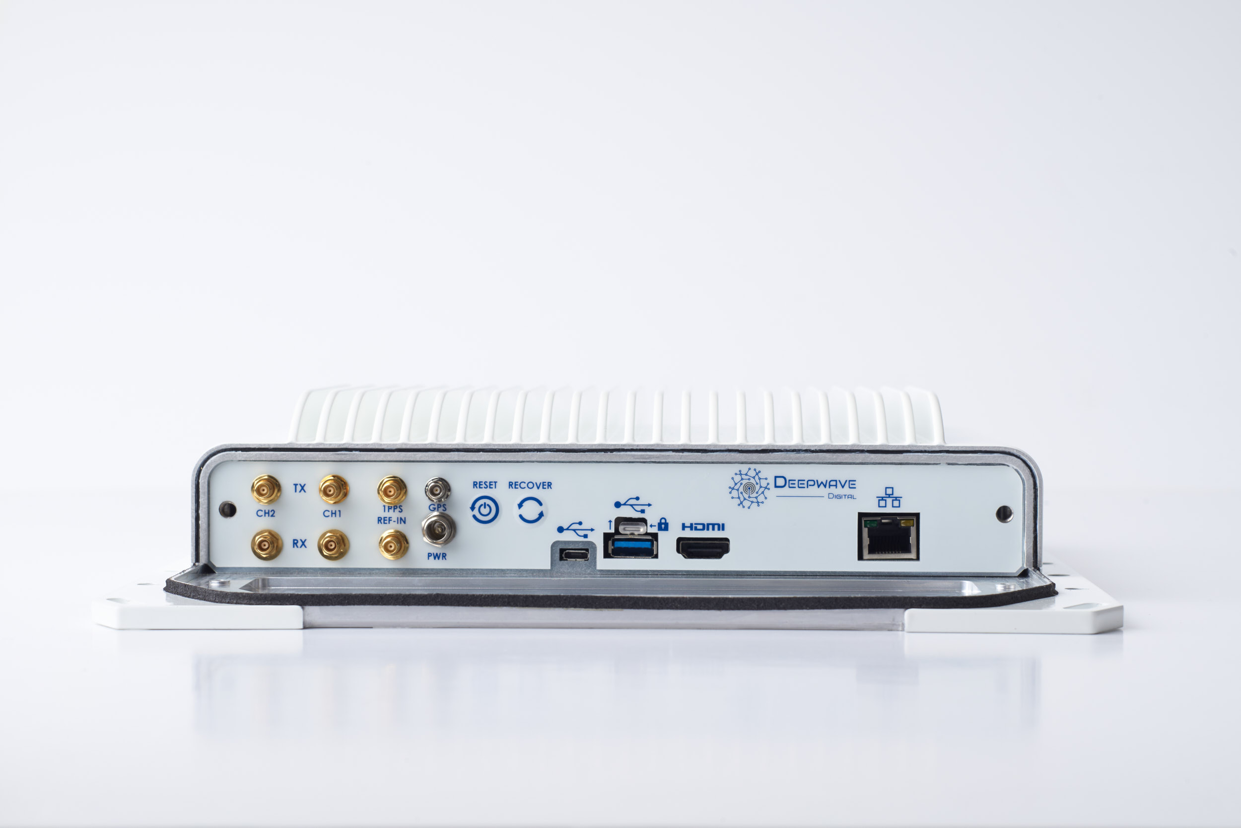
External Interfaces
Table 6 below describes the external interfaces to the Edge Series AIR-T. 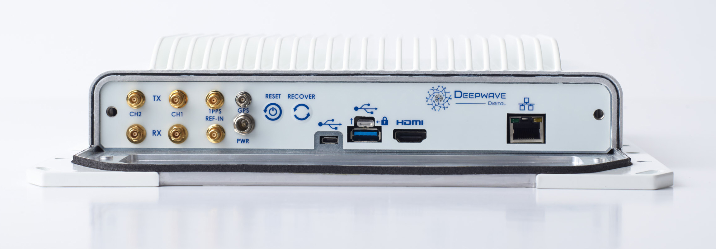
| Interface / Button | Description |
|---|---|
| Ethernet | 10/100/1000 BASE-T, RJ-45 connector |
| HDMI 2.0 a/b | Up to 3840 x 2160 at 60Hz (4k) |
| USB 3.0 | USB 3.0 Super Speed mode (up to 5Gb/s) |
| USB 2.0 | High Speed mode (up to 480Mb/s), USB On-The-Go |
| Recover | Used to place the unit in recovery mode |
| Reset | Power reset to the unit |
| GPS | GNSS antenna input |
| PWR | Power input |
| 1 PPS | Input for 1 PPS signal or trigger input |
| TX CH1 | Transmitter output for channel 1 |
| TX CH2 | Transmitter output for channel 2 |
| RX CH1 | Receiver input for channel 1 |
| RX CH2 | Receiver input for channel 2 |
A complete guide for selecting and installing cables may be found in our Cable Management for Edge Series guide.
Transceiver
Radio Frequency Integrated Circuit
The radio frequency integrated circuit (RFIC) on the AIR-T is the Analog Devices AD9371. This RFIC uses two local oscillators (LO): one for both transmit channels and one for both receive channels. This means that the transmitters and receivers may be tuned to different frequencies at the same time, but both transmit ports will always utilize the same common transmit frequency and both receive ports will always utilize the same common receive frequency.
In addition, the AIR-T Edge Series contains additional analog circuitry in the two channel receiver chain that improves the noise figure, gain, and extends the frequency range down to VHF.
The Edge Series AIR-T contains internal clocking circuitry to allow it to operate using an internal clock, have the user provide an external clock, or synchronize to the internal GNSS disciplined oscillator. For the external clock, the products will phase lock to an external 10 MHz reference signal with parameters defined in Table 11. The GPS interface is described in Table 12.
For additional details on the AD9371 please see that datasheet:
| Parameter | Value |
|---|---|
| Manufacturer | Analog Devices |
| Model | AD9371 |
| Frequency Conversion Type | Direct conversion |
| Parameter | Value |
|---|---|
| Number of Channels | 2 (LO shared) |
| Sample Rates (AIR8201) | Continuously variable between 125 to 3.906250 MSPS |
| Maximum Bandwidth | 100 MHz |
| Frequency Tuning Range | 30 MHz to 6 GHz |
| Gain | 52 dB |
| Noise Figure | 2.2 dB |
| Receiver Power Level Control | AGC or manual gain control (between 22-52 dB) |
| Maximum Input Power | +30 dBm |
| ADC Resolution | 16 bits |
| Built-in Calibrations | Quadrature Error Correction, DC offset correction |
| Parameter | Value |
|---|---|
| Transmit Channels | 2 (LO shared) |
| Sample Rates (AIR8201) | Continuously variable between 125 to 3.906250 MSPS |
| Maximum Bandwidth | 100 MHz |
| Frequency Tuning Range | 300 MHz to 6 GHz |
| Maximum Output Power | +6 dBm |
| Transmit Power Level Control | Manual gain control (between -36 and +6 dBm) |
| DAC Resolution | 14 bits |
| Built-in Calibrations | Quadrature Error Correction, LO leakage correction |
Timing Circuitry and Parameters
The AIR-T Edge Series SDR contains internal clocking logic that can leverage an internal reference, a user provided external reference, or the built-in GNSS disciplined oscillator. The following tables describe the parameters for each of these reference sources.
| Parameter | Value |
|---|---|
| Clock distribution part number | AD9528 |
| Oscillator Type | VCXO |
| Oscillator Model | Crystek Corporation CVHD-950-125M |
| Oscillator Frequency | 125 MHz |
| Frequency Pull Range | ± 20 ppm |
| Parameter | Value |
|---|---|
| Connector Type | MCX |
| Input Frequency | 10 MHz |
| Input Voltage Rating | 3.3V CMOS |
| Abs Maximum Voltage (50 Ohm) | 3.45 Volts |
| Parameter | Value |
|---|---|
| Connector Type | MCX |
| Oscillator Type | OCXO |
| 1 PPS Accuracy | 40 ns to UTC |
| Holdover Stability | <±400nsec @ 1 hour <±50usec @ 24 hours |
| GNSS Reception Capability | GPS L1C/A, GLONASS L1OF, Galileo E1B/E1C, QZSS L1C/A, QZSS L1S, SBAS L1C/A |
| Sensitivity | >162 dBm (acquisition and track) |
| Anti-jam | Eight automatic anti-jam countermeasures against CW signals |
| Antenna | Active (5V compatible) or Passive |
For detailed information on interfacing with the GNSS Diciplined Oscillator, see the Edge Series GNSS Guide.
Power
| Parameter | Value |
|---|---|
| Input Voltage Range | 8-15 VDC |
| Power Connector | 2.5mm ID long barrel (Switchcraft 761KH) |
For further information on designing a power cable for the Edge Series AIR-T, see the Cable Management for Edge Series page.
Mechanical and Environmental
| Parameter | Value |
|---|---|
| Dimensions | 28cm × 31cm x 6cm (11.0" × 12.2" x 2.4") |
| Operating Temperature Range | -40°C to +85°C |
| Ingress Protection Code | IP561 |
Proper Handling
The AIR-T Edge Series is thermally and environmentally sealed. Opening of the enclosure will void the warranty of the product.
During the calibration procedure that is run when the radio is initialized, calibration signals may be emitted from both the TX and RX ports. To ensure that connected equipment is not damaged, it is recommended to disconnect the AIR-T from any equipment and terminate with 50 Ohms during the radio initialization.
Warranty
Deepwave Digital Inc warrants that the Product will be free from defects in material and workmanship for a period of 12 months from the date of Deepwave Digital's shipment of the Product to the Customer. See the full warranty information here.
1 Certification pending